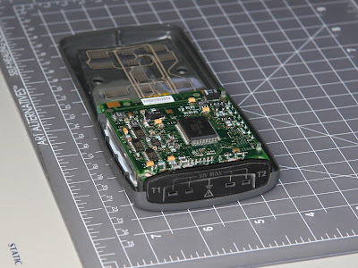
Have you ever designed cold-junction compensation (CJC) for a thermocouple front end? Let's see how Fluke did it. The point of interest in this thermometer is the small board responsible for CJC.
Progressively removing the case. The cold-junction compensation
board is not yet visible. It sits below the main board and behind the
black plastic plate with slots for thermocouple connector blades.
The cold-junction compensation board sits below the main board. The contact between the pads and thermocouple connector blades forms the
cold junctions, which the instrument has to compensate for. Since cold-junction compensation has its own daughter board, and it's somewhat insulated from temperature gradients that
may be generated by the main board.
Interestingly, the CJC board is made with metal (copper) substrate. It promotes heat transfer and reduces temperature gradient between the cold junctions and the sensor which measures their temperature. (The CJC temperature sensors are better visible on another photo below.)
Side view.
Thermocouple connector added to show where the contact between thermocouple materials and copper pads on the cold-junction compensation board takes place.
Cold-junction compensation sits on its own daughter board, and it's somewhat insulated from temperature gradients that
may be generated by the main board.

Main view of the cold-junction compensation board.
- SOT-23-3 ICs between each pair of the thermocouple pads are the sensors which measure the cold-junction temperature.
- An EEPROM (AT25010 ) suggests that the CJC board is calibrated separately from the main board and the coefficients are stored in this EEPROM.
- LT1034 is a dual voltage reference
Each blade of a thermocouple plug has an individual spring clip that presses the blade to the contact pad on the board.
Related
Maxim App Note 4026 Implementing Cold-Junction Compensation in Thermocouple Applications
Discussion about cold-junction compensation in this
Analog Dialogue article (2010).


