Sunday, October 18, 2015

I2C pull-up resistors on modules and breakout boards

I no longer maintain this page due to issues with SVG drawings on Blogspot.

The maintained copy of this page is here:
http://www.prolifictec.com/blog/2015/10/i2c-pull-up-resistors-on-modules-and-breakout-boards.html .

- Nick


Some of the modules and breakout boards for I2C slave devices contain I2C pull-up resistors. When multiple such modules are connected to the same I2C bus, their pull-up resistors appear in parallel.  That results in a stronger effective pull-up resistance, which may prevent communication on the I2C bus.

You have to have pull-ups on the I2C bus.

Somewhere on the  I2C bus you have to have pull-ups in order to be able to communicate on the I2C bus.  The pull-ups may reside on the microcontroller board, or on the I2C slave device's breakout board, or anywhere else on the I2C bus.

Some microcontrollers have internal pull-ups.  It's not recommended to use the microcontroller's internal pull-ups for I2C.  Still, internal pull-ups is much better than no pull-ups at all.

Watch out, though - you may end-up with pull-up that's too strong.

If pull-up resistors are too strong, that can prevent communication on the I2C bus.

Strong pull-up means that the current through the resistor is relatively large.  Stronger pull-up translates into smaller resistor value.  Weak  pull-up translates into a larger resistor value. 
(Stiff means the same as strong, when describing pull-up resistors.  This terminology is not limited to I2C.  It applies to pull-up and pull-down resistors in other types of circuits too.)

The unwanted pull-up resistors are shown in red.  These may create a pull-up that's too strong, which can prevent the communication on the I2C bus.

Suppose all three boards in this diagram came with pull-up resistors installed. The 2.2 kΩ value is common for an I2C bus running at +5V.  Notice however that R2, R4, R6 all are connected between SCL and Vdd.  They are in parallel, and they act as one 733 Ω resistor.  This combined pull-up is too strong I2C.  That can prevent communication on the I2C bus.  (Similar for the pull-up resistors on the SDA line.)

If these resistors can spoil the I2C bus, then why are they designed into the breakout boards in the first place?  I'm guessing that it must have been a compromise to create an easy out-of-the-box experience.  A lot of I2C first-timers don't know that pull-ups are required.  Some Arduino boards don't have I2C pull-up resistors nor pads for them (Arduino Uno, Arduino Pro, for example).  Some Arduino boards have unpopulated pads for I2C pull-up resistors (Arduino Mini Pro, for example).  A breakout board provides the pull-ups, and "it just works".  That is, until too many breakout boards are connected in parallel.

Remedies

Of course, as soon as you realize that there are extra pull-up resistors you can simply remove them.

Some breakout board suppliers are aware of the possible parallel pull-up scenario.  Many of the newer breakout boards have been designed with that in mind.
  • Perhaps to partially address this, some of the breakout boards have I2C pull-ups which are half strength.  They are weaker than the correct values for the I2C, but stronger than the internal pull-ups of a μC.  A typical such value is 4.7 kΩ .  This is a compromise.  The number of modules that can be connected in parallel without removing resistors is still limited. But a greater number of modules may be connected before combined parallel pull-up becomes too strong.
  • On some of the breakout boards, pull-up resistors are connected to Vcc through solder blobs.  A solder blob is easy to remove, then pull-up resistors will not affect the I2C bus.  (For example, see SJ1 in this SparkFun breakout board.)
  • Some breakout boards have unpopulated pads for pull-ups.  (For example, see R1 and R2 on this board.)

Related

I2C bus specification and user manual.  Anyone working with I2C should at least skim through it.
How to deal with multiple pull-up resistors on modules?  That forum question was a point of departure for writing this post.
A case when ATmega's internal pull-ups were used for I2C.  The oscilloscope screenshots show I2C waveforms with internal pull-ups, and with proper external pull-up resistors.
Forum thread Is there a correct resistance value for I2C pull-up resistors? and application note I2C Bus Pullup Resistor Calculation.
EDN article Design calculations for robust I2C communications.  Concise article with diagrams showing I2C physical layer principles of operation.
Effects of varying I2C pull-up resistors.  The article shows oscilloscope screenshots of good and bad I2C signals.
Pull-up resistor and pull-down resistor explained

Friday, August 14, 2015

When does the Arduino Wire library actually transmit on the I2C bus ?

I wanted to better understand the inner workings of the Wire library (the I2C library that comes with Arduino IDE).  The detailed reference and source code were helpful.  To check my understanding, I made a simple oscilloscope experiment, which I would like to report in this post.

Setup

Straightforward test code, which creates a write transaction on the I2C bus.  To know when the calls to the Wire library methods happen, each one is preceded by a strobe on pin 13.  These strobes will be seen with an oscilloscope.   To know when the I2C activity actually occurs, SDA and SCL (the I2C data and clock lines) are too observed with the oscilloscope.

  void strobe() {
    digitalWrite(13, HIGH);           // Strobe for oscilloscope
    digitalWrite(13, LOW);
  }
 
  void loop() {
    strobe();
    Wire.beginTransmission(0x4C);     // Set the address of the target device  
                                      // which we want to write to
    strobe();
    Wire.write(0x07);                 // Payload: set the address of the register inside
                                      // of the external device, which we want to write to
    strobe();
    Wire.write(0x01);                 // Payload: value to write to the register

    strobe();
    Wire.endTransmission();           // Actually do the transmission.

    delay(1000);
  }

This code ran on Arduino LilyPad USB (my clone thereof).  It should work the same on any Arduino that's based on AVR and has got hardware I2C.

(The addressee of this I2C transaction is an MMA7660 accelerometer.  It could have been just about any I2C slave device.)

Results and discussion

Debug strobes and the I2C activity.  All I2C activity takes place after the strobes.

As you can see, all of the I2C activity happens after all the calls to the Wire library methods have been made.
Wire.beginTransmission(...) doesn't actually begin the transmission, it only sets the I2C slave address for the forthcoming transmission.
Wire.write(...) doesn't actually transmit, it writes to a buffer in the Arduino's RAM.
Wire.endTransmission() actually causes the whole I2C transaction to happen from beginning to end.

Perhaps, the Wire Library functions could have names that better reflects inner workings.

References

[1]  Wire Library superficial reference
[2]  Wire Library detailed reference
[3]  Source code for Wire Library on GitHub

Saturday, June 27, 2015

Teardown of Mastech MS8268 multimeter


The advertising for this multimeter stated that it has "warning when incorrect banana jacks are used relative to function switch setting".  I got curious about how the meter detected the banana plugs.  At first, I thought that there is an optical proximity sensors under each jacks, but that was an incorrect guess.  Each jack has a momentary switch at the bottom.  The switch has an plastic plunger, which insulates the detection switch from the banana contacts.


Light pipes for ring indicators around banana jacks visible.
One of the light pipes, which forms the ring around a banana jack, is removed and shown separately on the right.
Red and black plastic parts inside of the banana jacks are the plungers which activate the detection switches.
The IC in the middle is a PIC microcontroller.  I suspect that it's main purpose is to detect leads, and to control the LEDs under the light pipes.

Mastech MS8268 multimeter with back cover removed. Fuse visible.


ICs in this meter, which I was able to identify
I bought this MS8268 multimeter to measure low currents on the order of units of microamps.  The miltimeter didn't disappoint, considering especially a relatively low price.

Related

Mastech MS8268 review
Teardown video (Dec 15)

Thursday, June 11, 2015

Teardown of a paddle wheel flow meter

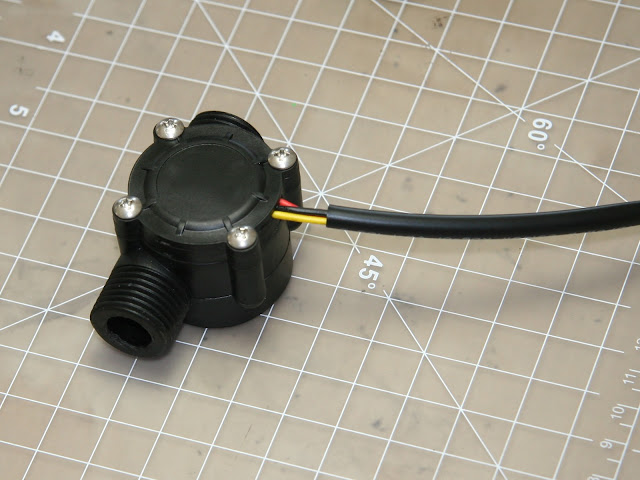
I'm setting up a control system for a small scale biofuel processing rig. Part of the task is to monitor the flow rate of feedstock. Due to budget constraints, I could not simply buy and industrial grade sensor. So, I'm evaluating this low cost sensor for low flow rate and more viscous fluid [than water].

This type of low-cost paddle wheel flow meter is sold by Adafruit among other places.

Assembled flow sensor before teardown

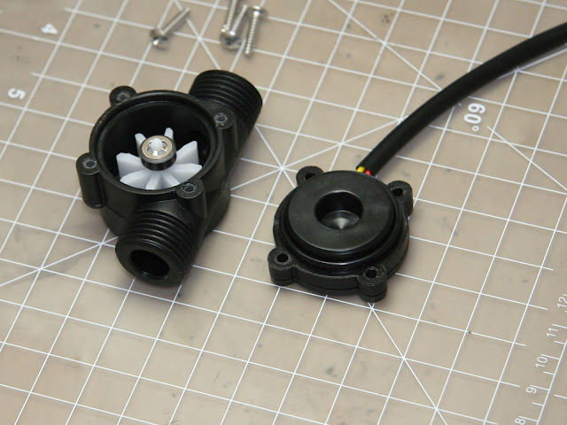
Cavity is open.  Top of the paddle wheel with the magnet visible inside the cavity.
The gap between the tips of the paddles and the cavity is about 2.5mm .  If the gap were smaller, this flow meter would be more sensitive at low speeds.

The static o-ring, which seals the paddle wheel cavity, is visible on the lid.  The latter also serves as the bottom of the PCB compartment.

At the end of the paddle wheel sits the magnet.  The outside diameter of the magnet is 9.7mm .

PCB compartment is open.  Component side of the PCB visible.

PCB with Hall effect sensor removed from its compartment

On the left side of the PCB stands the Hall effect sensor.  The writing on the IC is "W130".  I'm guessing it's Winson WSH130 (datasheet).  The Hall effect sensor sits 16.4mm from the axis.

The o-ring in this photo prevents liquid ingress into PCB compartment.  This is the 2nd o-ring in this device, and not the main one that seals the paddle cavity.

Reassembly

After this teardown, the reassembled sensor continued to work like new. 

Related

Sensors Magazine article on paddlewheel flow sensors
Higher precision paddle wheel flow sensors made by Omega Engineering

Disclaimer

I'm not affiliated with any of the companies mentioned in this post.

Saturday, June 6, 2015

How to make an educated guess about power ratings of common throughole resistors when datasheet is not available

This write-up is intended for beginners, perhaps for those who have logged less than 20 hours of building circuits.  You have a resistor in your hand, and you wonder: "Will it burn in my circuit? How much power can it dissipate?"

Maybe you are in a lab with a kit of resistors.  Somebody was kind enough to put the kit together, but the technical references for the resistors aren't readily available.  The maker of the kit knows the power ratings, but it's after hours, and he's not available.

I remember that in the first practicum of the introductory EE course we were instructed to "sacrifice" a quarter-watt resistor to see and smell how components burn.  The instructor would tell us matter-of-factly: "dial your power supply to 12V, take a 10Ω resistor, now connect the resistor to power supply with alligator clips."  It was a surprise for most students that the resistor immediately burned and smoked.

How much power will the resistor have to dissipate?

P = I2 R = V2 / R, where R is the value of your resistor.  Figure out a way to estimate the current through the resistor, or voltage across it.  Resistance is known.  Calculate power.

(To be more exact, it's VRMS or IRMS.  If the voltage and current approach DC, then the RMS value approaches the DC value.)

Attempt to look-up the power ratings.  Avoid guesswork if you can.

Even though this write-up is about educated guessing; guesswork should be last resort, not first.  Make an effort to find ratings provided by the curator of the kit or the supplier of resistors.  The raring may be written somewhere on the kit.  If the part number of the resistor is known, then you can look up the power rating in the datasheet.


Power rating of the resistors written on the package of this kit
Label of an 1/8-watt resistor kit. The information is there, if you look carefully.

How to make an educated guess about the power rating.

The larger the mechanical size of the resistor, the more power it can dissipate, the greater the power rating is.  So, it is possible to estimate the power rating of common** throughole based on outside dimensions. Measure the length and diameter and look-up the power rating in the table.


Power ratingBody length, lBody diameter, d
wattsinch [mm]inch [mm]
0.125 (1/8)0.130 ± 0.012 [3.30 ± 0.30]0.067 ± 0.012 [1.70 ± 0.30]
0.25 (1/4)0.236 ± 0.012 [6.00 ± 0.30]0.091 ± 0.012 [2.30 ± 0.30]
0.5 (1/2)0.335 ± 0.039 [8.50 ± 1.00]0.106 ± 0.020 [2.70 ± 0.50]

These dimensions come from the resistors' datasheets.  Since these axial throughole resistors are standardized, the datasheets from different manufacturers agree with each-other.


eighth-watt, quarter-watt, half-watt resistors side by side
Top to bottom: 1/8 watt, 1/4 watt, 1/2 watt resistors.
** Note, we are talking only about "garden variety" throughole resistors like the ones in the photo above.  We are not talking about power resistors like this or this.

What if you don't have the resistor with the required power rating on hand? 

1/4-watt is the most common size of a resistor that you will come across in hacker spaces, practicum labs in schools, and such.  1/4-watt is more than enough for small-signal circuits.  What if you calculations show that you need to dissipate more than 1/4 watt?  You have several options:
  • Procure a beefier resistor
  • Connect multiple resistors in series or parallel, such that their effective resistance has the desired value.  The combined power which they can dissipate will be equal to the sum of their power ratings.
  • Change your circuit to lower the power that the resistor would have to dissipate (perhaps temporarily until you procure a resistor with a sufficient power rating).

References

[1]  Datasheets for the "garden variety" axial throughole resistors: Stackpole Electronics, Philips, Panasonic, generic Chinese.  The datasheets agree with each-other, despite different manufacturers.  Common MIL standards were driving the design of resistors for a long time.

[2]  Resistor Sizes and Packages  


Sunday, May 24, 2015

Burning the bootloader into a clone of LilyPad Arduino USB using Arduino Mini-Pro

Synopsis: The well known ArduinoISP tutorial shows Arduino Uno for both target and ISP.  The same steps work without principal modifications for LilyPad Arduino USB as target and Arduino Mini-Pro as ISP.

Arduino Mini-Pro with attached wires.  The wires bring programming signal to the target ATmega32U4.  (Target not shown.)
Additional wires were soldered to the Mini-Pro to connect the programming signals to the target LilyPad clone. Screenshot.  Foreground: The bootloader have been downloaded. Windows have successfully recognized the Arduino LilyPad USB, and installed the driver for it.  Background: ArduinoISP sketch which was running on Arduino Mini-Pro.

Related

Using Arduino Nano as an ISP Programmer
ATmega bootloader programmer by Nick Gammon
Loading the Leonardo bootloader on the Adafruit ATMega32u4 breakout 

Tuesday, April 21, 2015

Difference between Sensors and Transducers

The question "What's the difference between sensor and transducer?" comes up in the web forums once in a while.  I suspect that university professors assign this question to their students.  It prompts the students to examine the signal chain of various sensors.  It also prompts the students to examine the purpose of the sensors and transducers within larger systems.

Working definitions

A transducer is defined as a device that converts some form of energy into another.
 This definition is rooted in physics.  I saw this definition in several books (from 60s and 70s). 

A sensor is a subsystem which converts the stimulus from the physical environment into the signal interpretable by the rest of the system.
To be effective, a sensor needs to do more than just convert one form of energy into another. 
The sensor need to distinguish its target stimulus from interference.  A sensor should have an output in a form which is convenient for the rest of the system

A sensing element is a part of a sensor directly affected by the stimulus and makes initial conversion into electrical domain.  Often sensing element is a transducer (in the pure physical meaning of a term).

Discussion

A transducer can be in a role of a sensing element, or an actuator, or sometimes even both.

A good example that illustrates the practical difference between transducers and sensors is a piezo.  The piezo transducers are used in a variety of sensors measure quite different parameters (range or flow velocity, for example).  Imagine that you want to measure flow speed of air in a duct.  If you have only a transducer in your hand, you would have to spend an appreciable amount of time before you become capable of actually making a measurement.  You would have turned the piezo transducer into a flow sensor by then.

In the industry, the usage of words "sensor" and "transducer" is a matter of convention.  Some industries use the term "transducer" for both sensors and transducers.

Related

http://www.sensorland.com/GlossaryPage001.html
http://www.softnoze.com/glossary-of-automation-sensing-and-switching-terms.cfm
https://www.nap.edu/read/4782/chapter/15#107
Several glossaries for sensors terms.  Some of them have a definition for transducer.  None of them have a definition for a sensor (oddly enough).

https://groups.yahoo.com/neo/groups/sensorforum/conversations/messages/126
My earlier version of this post from 2007.