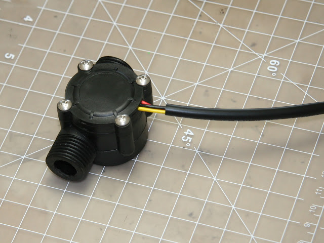
I'm setting up a
control system for a small scale biofuel processing rig. Part of the
task is to monitor the flow rate of feedstock. Due to budget
constraints, I could not simply buy and industrial grade sensor. So,
I'm evaluating this low cost sensor for low flow rate and more
viscous fluid [than water].
This type of low-cost paddle wheel flow meter is sold by Adafruit among other places.
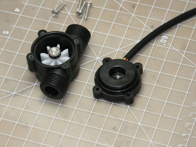
The static o-ring, which seals the paddle wheel cavity, is visible on the lid. The latter also serves as the bottom of the PCB compartment.
At the end of the paddle wheel sits the magnet. The outside diameter of the magnet is 9.7mm .
The o-ring in this photo prevents liquid ingress into PCB compartment. This is the 2nd o-ring in this device, and not the main one that seals the paddle cavity.
Reassembly
After this teardown, the reassembled sensor continued to work like new.Related
Sensors Magazine article on paddlewheel flow sensorsHigher precision paddle wheel flow sensors made by Omega Engineering


No comments:
Post a Comment